Programming a PLC can sometimes be a daunting task. The best method is to break the task into some smaller steps. These are the steps that I have used for years to develop PLC programs. We will apply them to a die stamping application.
Step 1 – Define the task:
What has to happen? This is written down and summarized. You may have to ask several different people how the machine is to operate. Going back to individuals when there is a conflict on specific aspects of the operation. This step is number one for a reason with PLC program development.
A master switch is used to start the process and to shut it down. Two sensors: an upper limit switch that indicates when the piston is fully retracted and a lower limit switch that indicates when the piston is fully extended. When the master switch is turned on the piston reciprocates between the extended and retracted positions. This is achieved with an up and down solenoid. When the master switch is turned off, the piston returns to the retracted position, and all solenoids are off.
Step 2 – Define the Inputs and Outputs:
Based on the information in step 1, you determine the inputs and outputs to the PLC required to develop what has to happen.
Outputs: Down Solenoid – On/Off Up Solenoid – On/Off
Step 3 – Develop a logical sequence of operation:
This is where the majority of time is spent in PLC program development. Steps 1 and 2 allow you to systematically express what has to happen in the PLC program. Based on the logic, you may have to modify the inputs/outputs or sequence of the program. This is the easiest place to make changes.
This can be done with the use of a flow chart or sequence table. You can use anything to fully understand the logic of the operation before programming. Many people do not use this step and jump straight to programming.
Fully understanding the logic before starting to program can save you time and frustration.
Sequence Table: The following is a sequence table for our die stamping application. I usually review this sequence with the person with the most knowledge of the machine. This can be the designer and/or the machine operator.
How to read the Sequence Table: Follow the steps from left to right, top to bottom. Inputs and outputs are labeled as 1 (ON), 0 (OFF) or X (Does not Matter). Step 1 indicates that it does not matter the upper and lower limit switch positions. The master switch is off, so the up and down solenoids are off. Steps 3 and 4 repeat themselves as long as the master switch is on.
Note: You will notice that at step 2 after the master switch turns on the up solenoid will be activated. So the piston always retracts when the master switch is first turned on. This operation was picked up in the development of our logical sequence.
Step 4 – Develop the PLC program:
Utilizing the above steps, we will now actually write the plc program. This can be in several different languages. In our case, ladder logic will be used.
Look at the sequence table with respect to the following logic. I have used Set and Reset conditions so it is easily followed by the sequence table. When the master switch turns on the up solenoid is activated. Notice the first rung is a direct correlation. Follow the rest of the sequence table with this ladder logic.
Document, Document, Document This is a vital part of every program, which will save you time and money when you have to return to the program years later.
Step 5 – Test the program:
Test the logic that you have developed. Once again the previous steps are helpful in this process. PLC program development testing is an important step to test for all conditions of the logic. (Power Cycle, Sensors Fail, Safety, etc.)
Test the program with a simulator or actual machine. Make modifications as necessary. Check with the people most knowledgeable on the machine, to see if it is doing what they expect. Do they need anything else? Follow up after a time frame to see if any problems arise that need to be addressed.
These five steps will help you in your PLC program development.
Define the task
Define the inputs and outputs
Develop a logical sequence of operation
Develop the PLC program
Test the program
The five steps form the basis of all PLC development. You will notice that the actual programming does not occur until the second last step. Usually, more time is spent on understanding the task and sequence of operation.
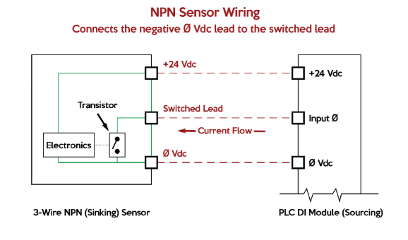
Sensor Connections: PNP versus NPN and Sourcing versus Sinking
산업자동화에는 24V용 센서가 주로 사용되며, NPN, PNP 두가지 타입이 있습니다. 두가지 타입의 센서는 PLC의 DI(Discrete Input) 모듈의 두가지 타입인 소스방식과 싱크방식에 맞춰서 사용해야 합니다.
Transistor Effects
ON-OFF 형태의 신호를 다루는 전자장치(예를 들어, 입력센서)는 트랜지스터를 내장하고 있습니다. 트랜지스터는 반도체 재질의 소형 릴레이이며, 전류를 흐르거나 차단하는 스위치와 같은 역할을 합니다. 트랜지스터는 약한 신호를 감지후 신호를 증폭하는 역할도 하게 됩니다. 증폭된 신호는 PLC의 입력모듈 또는 기타 장치들로 전달될 수 있습니다. 트랜지스터는 NPN(sourcing), PNP(sinking) 두가지 타입이 있습니다.
"P", "N"은 반도체 물질의 종류를 의미하며, "PNP", "NPN"은 이 물질들의 배열순서를 의미합니다. 트랜지스터는 base, collector, emitter로 구성된 3개의 핀을 가지고 있습니다.
PNP versus NPN Switching
산업용 3선식 센서는 대부분 아래와 같은 선으로 구성되어 있습니다.
* +24 Vdc
* 0 Vdc
* 신호선
+24 Vdc, 0 Vdc 선은 센서의 구동에 필요한 전원공급용이며, NPN, PNP타입은 신호선이 어떻게 구동될 것인지 결정하게 됩니다.
PNP 타입의 센서는 emitter에 +24 Vdc가 인가되고, collector에 sinking 타입 PLC 모듈과 연결됩니다. 센서가 특정한 물체를 감지하면 base에 전류를 흐르게 하여 emitter-collector간 전류가 흐르게 됩니다. 즉, 신호선쪽으로 +24 Vdc가 인가되고, PLC의 sink 타입 입력모듈 단자를 통해 포토커플러(빛을 이용하여 전류를 흐르게 하는 스위치. 입력모듈이 입력을 확인하는 용도로 사용)를 거친후 0 Vdc로 이어지게 됩니다.
NPN 타입의 센서는 emitter에 0 Vdc가 인가되고, collector에 source 타입 PLC 모듈과 연결됩니다. 센서가 특정한 물체를 감지하면 base에 전류가 흐르게 하여 collector-emitter간 전류가 흐르게 됩니다. 즉, 신호선쪽으로 0 Vdc가 인가되고, PLC의 source 타입 입력모듈 단자를 통해 포토커플러를 거친후 +24 Vdc로 이어지게 됩니다.
Three-Wire Devices and Leakage Current
3선식 센서는 트랜지스터 특성상 누설전류가 발생합니다. 센서가 신호선 스위치를 OFF하고 있음에도 신호선을 통하여 미세하게 전류가 흐르는 현상입니다. 비정상적으로 높은 누설전류는 의도치 않게 PLC의 입력모듈내 포토커플러를 동작시켜 마치 센서가 무언가를 감지한 것처럼 인식하게 만들수 있습니다.
Sourcing versus Sinking Circuits
sinking(싱크방식) 입력모듈은 PNP 센서와 사용되며, 입력모듈은 센서 감지시 신호선에 +24 Vdc가 인가되길 기다리고 있습니다.
sourcing(소스방식) 입력모듈은 NPN 센서와 사용되며, 입력모듈은 센서 감지시 신호선에 0 Vdc가 인가되길 기다리고 있습니다.
PLC 기종의 따라 sinking/sourcing를 반대로 표기하는 경우도 있으니, 입력모듈의 결선도는 꼭 확인해 보는 것이 좋습니다.
Benefits of PNP versus NPN
PNP 타입의 센서는 케이블 손상시 신호선과 0 Vdc선이 단락될 경우가 있을 수 있습니다. 그 결과로 센서가 손상될 것입니다.
NPN 타입의 센서는 케이블 손상시 신호선과 0 Vdc이 단락될 경우가 있을 수 있습니다. 그 결과로 입력모듈에 계속 신호가 들어오는 형태가 되지만 센서가 손상되지는 않습니다.
Before the advent of solid-state logic circuits, logical control systems were designed and built exclusively around electromechanical relays. Relays are far from obsolete in modern design, but have been replaced in many of their former roles as logic-level control devices, relegated most often to those applications demanding high current and/or high voltage switching.
Systems and processes requiring “on/off” control abound in modern commerce and industry, but such control systems are rarely built from either electromechanical relays or discrete logic gates. Instead, digital computers fill the need, which may beprogrammedto do a variety of logical functions.
The History of Programmable Logic Controllers
In the late 1960’s an American company named Bedford Associates released a computing device they called theMODICON. As an acronym, it meantModularDigitalController, and later became the name of a company division devoted to the design, manufacture, and sale of these special-purpose control computers.
Other engineering firms developed their own versions of this device, and it eventually came to be known in non-proprietary terms as aPLC, orProgrammableLogicController. The purpose of a PLC was to directly replace electromechanical relays as logic elements, substituting instead a solid-state digital computer with a stored program, able to emulate the interconnection of many relays to perform certain logical tasks.
Ladder Logic and Programming PLCs
A PLC has many “input” terminals, through which it interprets “high” and “low” logical states from sensors and switches. It also has many output terminals, through which it outputs “high” and “low” signals to power lights, solenoids, contactors, small motors, and other devices lending themselves to on/off control.
In an effort to make PLCs easy to program, their programming language was designed to resembleladder logic diagrams. Thus, an industrial electrician or electrical engineer accustomed to reading ladder logic schematics would feel comfortable programming a PLC to perform the same control functions.
PLCs are industrial computers, and as such their input and output signals are typically 120 volts AC, just like the electromechanical control relays they were designed to replace. Although some PLCs have the ability to input and output low-level DC voltage signals of the magnitude used in logic gate circuits, this is the exception and not the rule. Signal connection and programming standards vary somewhat between different models of PLC, but they are similar enough to allow a “generic” introduction to PLC programming here.
The following illustration shows a simple PLC, as it might appear from a front view. Two screw terminals provide connection to 120 volts AC for powering the PLC’s internal circuitry, labeled L1 and L2. Six screw terminals on the left-hand side provide connection to input devices, each terminal representing a different input “channel” with its own “X” label.
The lower-left screw terminal is a “Common” connection, which is generally connected to L2 (neutral) of the 120 VAC power source.
Inside the PLC housing, connected between each input terminal and the Common terminal, is an opto-isolator device (Light-Emitting Diode) that provides an electrically isolated “high” logic signal to the computer’s circuitry (a photo-transistor interprets the LED’s light) when there is 120 VAC power applied between the respective input terminal and the Common terminal. An indicating LED on the front panel of the PLC gives visual indication of an “energized” input:
Output signals are generated by the PLC’s computer circuitry activating a switching device (transistor, TRIAC, or even an electromechanical relay), connecting the “Source” terminal to any of the “Y-” labeled output terminals. The “Source” terminal, correspondingly, is usually connected to the L1 side of the 120 VAC power source. As with each input, an indicating LED on the front panel of the PLC gives visual indication of an “energized” output:
In this way, the PLC is able to interface with real-world devices such as switches and solenoids. The actuallogicof the control system is established inside the PLC by means of a computer program. This program dictates which output gets energized under which input conditions.
Although the program itself appears to be a ladder logic diagram, with switch and relay symbols, there are no actual switch contacts or relay coils operating inside the PLC to create the logical relationships between input and output. These areimaginarycontacts and coils, if you will. The program is entered and viewed via a personal computer connected to the PLC’s programming port. Consider the following circuit and PLC program:
When the pushbutton switch is unactuated (unpressed), no power is sent to the X1 input of the PLC. Following the program, which shows a normally-open X1 contact in series with a Y1 coil, no “power” will be sent to the Y1 coil. Thus, the PLC’s Y1 output remains de-energized, and the indicator lamp connected to it remains dark.
If the pushbutton switch is pressed, however, power will be sent to the PLC’s X1 input. Any and all X1 contacts appearing in the program will assume the actuated (non-normal) state, as though they were relay contacts actuated by the energizing of a relay coil named “X1”.
In this case, energizing the X1 input will cause the normally-open X1 contact will “close,” sending “power” to the Y1 coil. When the Y1 coil of the program “energizes,” the real Y1 output will become energized, lighting up the lamp connected to it:
(푸시버튼(X1)을 누르고 있는 상태에서만 Y1(전등)이 켜져있다. )
It must be understood that the X1 contact, Y1 coil, connecting wires, and “power” appearing in the personal computer’s display are allvirtual. They do not exist as real electrical components. They exist as commands in a computer program—a piece of software only—that just happens to resemble a real relay schematic diagram.
Equally important to understand is that the personal computer used to display and edit the PLC’s program is not necessary for the PLC’s continued operation. Once a program has been loaded to the PLC from the personal computer, the personal computer may be unplugged from the PLC, and the PLC will continue to follow the programmed commands.
I include the personal computer display in these illustrations for your sake only, in aiding to understand the relationship between real-life conditions (switch closure and lamp status) and the program’s status (“power” through virtual contacts and virtual coils).
Control System Behavior
The true power and versatility of a PLC is revealed when we want to alter the behavior of a control system. Since the PLC is a programmable device, we can alter its behavior by changing the commands we give it, without having to reconfigure the electrical components connected to it.
For example, suppose we wanted to make this switch-and-lamp circuit function in an inverted fashion: push the button to make the lamp turnoff, and release it to make it turnon. The “hardware” solution would require that a normally-closed pushbutton switch be substituted for the normally-open switch currently in place. The “software” solution is much easier: just alter the program so that contact X1 is normally-closed rather than normally-open.
In the following illustration, we have the altered system shown in the state where the pushbutton is unactuated (notbeing pressed):
(X1을 B접점(Normal Close)으로 하면, 푸시버튼을 누르지 않는 상태에서 전등(Y1)이 켜져있다. )
In this next illustration, the switch is shown actuated (pressed):
(X1을 B접점(Normal Close)으로 하면, 푸시버튼을 누르면, 전등(Y1)은 꺼진다. )
One of the advantages of implementing logical control in software rather than in hardware is that input signals can be re-used as many times in the program as is necessary. For example, take the following circuit and program, designed to energize the lamp if at least two of the three pushbutton switches are simultaneously actuated:
(And와 Or로 연결된 구성으로, X1, X2, X3중 어떠한 2개의 푸시버튼을 눌르면, 전등이 켜진다. )
To build an equivalent circuit using electromechanical relays, three relays with two normally-open contacts each would have to be used, to provide two contacts per input switch. Using a PLC, however, we can program as many contacts as we wish for each “X” input without adding additional hardware, since each input and each output is nothing more than a single bit in the PLC’s digital memory (either 0 or 1), and can be recalled as many times as necessary.
Furthermore, since each output in the PLC is nothing more than a bit in its memory as well, we can assign contacts in a PLC program “actuated” by an output (Y) status. Take for instance this next system, a motor start-stop control circuit:
(X1은 On 스위치로 사용되고, X2는 Off스위치로 사용된다. )
The pushbutton switch connected to input X1 serves as the “Start” switch, while the switch connected to input X2 serves as the “Stop.” Another contact in the program, named Y1, uses the output coil status as a seal-in contact, directly, so that the motor contactor will continue to be energized after the “Start” pushbutton switch is released. You can see the normally-closed contact X2 appear in a colored block, showing that it is in a closed (“electrically conducting”) state.
If we were to press the “Start” button, input X1 would energize, thus “closing” the X1 contact in the program, sending “power” to the Y1 “coil,” energizing the Y1 output and applying 120 volt AC power to the real motor contactor coil. The parallel Y1 contact will also “close,” thus latching the “circuit” in an energized state:
(X1을 누르면, Y1의 출력이 발생하고, 이와 동시에 Y1의 입력이 발생한다. )
Now, if we release the “Start” pushbutton, the normally-open X1 “contact” will return to its “open” state, but the motor will continue to run because the Y1 seal-in “contact” continues to provide “continuity” to “power” coil Y1, thus keeping the Y1 output energized:
(Y1을 다시 입력으로 사용하면, X1의 버튼을 누르고 있지 않아도, Y1(전등)의 출력을 유지 한다. -자기유지 )
To stop the motor, we must momentarily press the “Stop” pushbutton, which will energize the X2 input and “open” the normally-closed “contact,” breaking continuity to the Y1 “coil:”
(X2를 누르면, Ladder상에서 B접점으로 된 X2로 인해서 Y1이 Off되고, 동시에 Y1입력도 Off가 된다.)
When the “Stop” pushbutton is released, input X2 will de-energize, returning “contact” X2 to its normal, “closed” state. The motor, however, will not start again until the “Start” pushbutton is actuated, because the “seal-in” of Y1 has been lost:
(X2의 푸시버튼을 다시 Release해도, 이미 X1입력 또는 Y1입력이 Off이기 때문에 Y1출력은 Off상태를 유지한다. )
Fail-safe Design in PLC-Controlled Systems
An important point to make here is thatfail-safedesign is just as important in PLC-controlled systems as it is in electromechanical relay-controlled systems. One should always consider the effects of failed (open) wiring on the device or devices being controlled. In this motor control circuit example, we have a problem: if the input wiring for X2 (the “Stop” switch) were to fail open, there would be no way to stop the motor!
The solution to this problem is a reversal of logic between the X2 “contact” inside the PLC program and the actual “Stop” pushbutton switch:
When the normally-closed “Stop” pushbutton switch is unactuated (not pressed), the PLC’s X2 input will be energized, thus “closing” the X2 “contact” inside the program. This allows the motor to be started when input X1 is energized, and allows it to continue to run when the “Start” pushbutton is no longer pressed. When the “Stop” pushbutton is actuated, input X2 will de-energize, thus “opening” the X2 “contact” inside the PLC program and shutting off the motor.
So, we see there is no operational difference between this new design and the previous design. However, if the input wiring on input X2 were to fail open, X2 input would de-energize in the same manner as when the “Stop” pushbutton is pressed. The result, then, for a wiring failure on the X2 input is that the motor will immediately shut off.
This is a safer design than the one previously shown, where a “Stop” switch wiring failure would have resulted in aninabilityto turn off the motor. In addition to input (X) and output (Y) program elements, PLCs provide “internal” coils and contacts with no intrinsic connection to the outside world. These are used much the same as “control relays” (CR1, CR2, etc.) are used in standard relay circuits: to provide logic signal inversion when necessary.
To demonstrate how one of these “internal” relays might be used, consider the following example circuit and program, designed to emulate the function of a three-inputNAND gate. Since PLC program elements are typically designed by single letters, I will call the internal control relay “C1” rather than “CR1” as would be customary in a relay control circuit:
In this circuit, the lamp will remain lit so long asanyof the pushbuttons remain unactuated (unpressed). To make the lamp turn off, we will have to actuate (press)allthree switches, like this:
Advanced PLC Functionality
This section on programmable logic controllers illustrates just a small sample of their capabilities. As computers, PLCs can perform timing functions (for the equivalent of time-delay relays), drum sequencing, and other advanced functions with far greater accuracy and reliability than what is possible using electromechanical logic devices. Most PLCs have the capacity for far more than six inputs and six outputs. The following photograph shows several input and output modules of a single Allen-Bradley PLC.
With each module having sixteen “points” of either input or output, this PLC has the ability to monitor and control dozens of devices. Fit into a control cabinet, a PLC takes up little room, especially considering the equivalent space that would be needed by electromechanical relays to perform the same functions:
Remote Monitoring and Control of PLCs Via Digital Computer Networks
One advantage of PLCs that simplycannotbe duplicated byelectromechanical relaysis remote monitoring and control via digital computer networks. Because a PLC is nothing more than a special-purpose digital computer, it has the ability to communicate with other computers rather easily. The following photograph shows a personal computer displaying a graphic image of a real liquid-level process (a pumping, or “lift,” station for a municipal wastewater treatment system) controlled by a PLC.
The actual pumping station is located miles away from the personal computer display: